1

Coupled reservoir-wellbore model initialization (using T2Well)
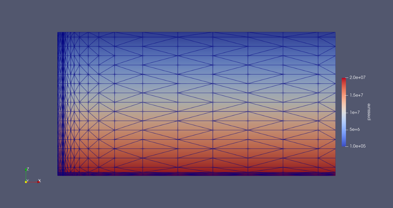
Hello everyone,


I have started using T2Well to simulate coupled reservoir-wellbore problems recently. While initializing the numerical model, I find the following problem; I have followed the same procedure that I follow with TOUGH3 to initialize the simulation. I have specified pressure and temperature for the grid cells which follow hydrostatic and  geothermal gradient, respectively (as illustrated in the attached photos). I have tried to run the model with no generation terms to make sure that the model attains steady state conditions while observing pressure and temperature results in the specified monitoring well. I find strange behavior; temperature and pressure in the monitoring well oscillate!. I am not sure what is the reason for this behavior. I put the relative tolerance small value (1E-8) to obtain accurate initial results. This behavior occurs only in the wellbore cells; reservoir cells show steady state pressure and temperature results.  


Thanks in advance. 

17 replies

null
    • Staff Scientist
    • Christine_Doughty
    • 4 yrs ago
    • Reported - view

    I recommend making the permeability of the well material equal to the reservoir permeability for the initialization run.  With no sources or sinks, it does not need to have high permeability. Don't forget to change it back for your main simulation!

      • Refaat_G_Hashish
      • 4 yrs ago
      • Reported - view

      Christine Doughty Dr. Christine,

      Thanks for your reply. I have initialized the model using TOUGH3 to get the INCOND data that satisfy hydrostatic pressure gradient and geothermal temperature gradient. I have used the obtained initial conditions in the attached input file, however I find similar behavior during the simulation run.  

    • Staff Scientist
    • Christine_Doughty
    • 4 yrs ago
    • Reported - view

    Try decreasing the wellbore permeability by a factor of 10.  If that does not help decrease it more.  You want wellbore permeability to be very high compared to reservoir permeability, but I have had trouble in the past with too high values, similar to what you are seeing.  I was able to find a permeability that was high enough to act like a wellbore, but low enough to run without oscillations.  I hope you can too.

      • Refaat_G_Hashish
      • 4 yrs ago
      • Reported - view

      Christine Doughty Thank you for your reply. I could initialize the model and run the simulation, however I find the time step decreases after ~ 20 days to zero. I find the following message repeated in OUTPUT file.

      +++++++++ REDUCE TIME STEP AT ( 574,  2) ++++++++++++++++   NEW DELT = 0.259702E-13
       ...ITERATING...  AT [ 574,  1] --- DELTEX = 0.259702E-13   MAX. RES. = 0.116129E-15  AT ELEMENT A5B14  EQUATION   3
       A2B14( 574,  2) ST = 0.177067E+07 DT = 0.259702E-13 DX1= -.139950E-09 DX2= -.108259E-27 T =  29.904 P =  5541966. S = 0.999998E+00
       ...ITERATING...  AT [ 575,  1] --- DELTEX = 0.339950E-13   MAX. RES. = 0.152013E-15  AT ELEMENT A5B14  EQUATION   3
       A5B14( 575,  2) ST = 0.177067E+07 DT = 0.339950E-13 DX1= 0.565840E-09 DX2= 0.283254E-20 T =  30.598 P =  6099348. S = 0.751686E+00
       ...ITERATING...  AT [ 576,  1] --- DELTEX = 0.444995E-13   MAX. RES. = 0.198985E-15  AT ELEMENT A5B14  EQUATION   3
       ...ITERATING...  AT [ 576,  2] --- DELTEX = 0.444995E-13   MAX. RES. = 0.353927E+01  AT ELEMENT *1B14  EQUATION   3
       ****************************
       tx=   1.00000000000000      in eos from X   10000.0000000000     
       -9.697624619792246E-014   10.9965500718375        1.00000000000000       at n=
              7076
        TEMPERATURE =0.100000E+01  SALT FRACTION = 0.000000E+00  OUT OF RANGE IN SATB 
       failed in SATB
       +++++++++   CANNOT FIND PARAMETERS AT ELEMENT **1B14*          XX(M) = 0.100000E+05 0.000000E+00 0.109966E+02 0.100000E+01
       failed in EOS,igood=           2


      I am not sure what is SATB. I guess that temperature results are beyond the range of EOS.  Parameter *1B14 represents wellhead in my case.  

    • Staff Scientist
    • Christine_Doughty
    • 4 yrs ago
    • Reported - view

    I think you are correct that T=1 is too small for the EOS you are using.  SATB is just the name of the subroutine where the code fails, but the important thing here is that for some reason the temperature has dropped out of bounds of the EOS and the code can't continue (takes tiny steps) because it does not know what any temperature-dependent properties are.  Without knowing more about your problem I cannot guess why temperature has dropped so much.  Unfortunately, I am not an experienced T2Well user.  My general strategy when primary variables go out of bounds is to think about the physics of the problem.  For example, if P is getting way too big, maybe you are injecting at too high a rate for the permeability you have.  It can help to figure things out to use the FOFT block to choose several elements to watch over time - certainly you should be watching *1B14 and maybe other wellbore elements.  It would be helpful to know if T was gradually decreasing for the whole 20 days, or if something happened around day 20 to cause T to suddenly drop.  Similarly, if you make spatial plots of T at a series of times, it might help.  Also, you might be able to make the problem easier by turning off certain features, then once you have a stable case, turn the features back on one by one to see what causes problems.   Good luck!

      • Refaat_G_Hashish
      • 4 yrs ago
      • Reported - view

      Christine Doughty Thank you for your reply. I expect gradual decrease of temperature and it may decrease to the freezing point of water.  My problem is a reservoir that has two wells; an injector well and monitoring well. I am trying to observe the changes in p, T, and CO2 saturation at the monitoring well during the injection. The monitoring well, which is modeled using T2Well, extends to the surface, however the injection well is modeled by assigning Dirichlet temperature conds at the reservoir grids which represent the injector.

      I  have the following comment on yours reply. As I am modeling the monitoring well using T2Well NOT EPM (Equivalent Porous Media), why does the permeability of the well affect the simulation results?   In the input file, I have to provide the following properties (porosity, absolute permeability, and relative permeability) for the grids that constitute the monitoring well which is modeled using T2Well, but I am not sure why they  have to be inserted.

      wells    2  2600.e00    1.0000  100.e-15  100.e-15  100.e-15      2.51      920.
         0.0e-10                         
          7           .457       .30        1.       .05
          8 

      • Mo_haseeb
      • 5 mths ago
      • Reported - view


      Would you happen to have any instructional material that gives step by step guidelines for this whole process. It can be as detailed or simple as you'd like. It will help me greatly.

      • Staff Scientist
      • Christine_Doughty
      • 5 mths ago
      • Reported - view


      Sorry, but I do not know of any step-by-step guidelines for using T2Well. The User's Guide is the best place to start. Many TOUGH-related topics other than T2Well are also covered in the Training material. Go to https://tough.lbl.gov/events/tough-short-courses/ and scroll all the way down to the bottom.

    • Staff Scientist
    • Christine_Doughty
    • 4 yrs ago
    • Reported - view

    I am generally familiar with how T2Well works, but I have not actually used it.  I recommend that you look at the user's guide, and examine the governing equations for wellbore flow to see whether porosity, absolute permeability, and relative permeability are used.  

    In terms of a well going to the surface with CO2 in the problem, you need to be careful about possible CO2 phase changes from supercritical to liquid or gas.  I believe you are using ECO2N as the equation of state, and it only allows one CO2 phase at a time to be present, so you have to avoid the liquid/gas saturation line and the critical point.  See the figure below for the CO2 phase diagram and a couple of possible paths from depth to the surface.  Both avoid the critical point and saturation line, but the one shown with black dots gets pretty close, which can cause numerical difficulties.

      • Sunny_Dai
      • 8 mths ago
      • Reported - view


      • Doctor, can you take a look at my question? thanks
      • Staff Scientist
      • Christine_Doughty
      • 8 mths ago
      • Reported - view


      When you say temperature gradient disappearance, do you mean that you specify a vertical temperature gradient as an initial condition, and after the code runs for a while, temperatures even out and you end up with a constant temperature?  If that is the case, make sure that you have constant-temperature boundaries at the top and bottom of the model, to fix the gradient.  Alternatively, you could put a heat source at depth (to represent the natural-state heat flow of the region) and hold the top boundary fixed to represent the average surface temperature.    

      Remember that normally in TOUGH, to make a constant-property boundary, you specify a huge volume for the element (~1.E30 m3), but if you just want a constant temperature but not a constant pressure, use a normal volume and set the rock specific heat to a huge value for the materials making up the boundaries.

      • Sunny_Dai
      • 8 mths ago
      • Reported - view


      The top boundary volume of the model is e50 and the temperature is 50 ℃ ; The bottom boundary density of the model is e30 and the temperature is 53 ℃,The output result is that the temperature of all grids is 50 ℃. I want to know why? 

      Today, I obtained the temperature gradient by increasing the temperature to 60 ℃ and 63 ℃. I was wondering if it was the reason for the phase transition, but at 16MPa, both 50 and 60 degrees are supercritical carbon dioxide.

      Best wish to you


      • Sunny_Dai
      • 8 mths ago
      • Reported - view

       This is my file, please take a look,thx

      • Staff Scientist
      • Christine_Doughty
      • 8 mths ago
      • Reported - view


      In flow.inp, there is a typo: the keyword to specify initial temperature for a material is INDOM.  TOUGH reads "INCOM" and does not recognize it as a keyword, so skips it.  (If you look at your output file, this should be documented near the beginning).  Thus your model is initialized all at 50C.  Maybe when you ran at 60 and 63 degrees C, you corrected the typo?

      • Sunny_Dai
      • 8 mths ago
      • Reported - view

       I made a basic mistake, sorry for taking up everyone's time

      • Staff Scientist
      • Christine_Doughty
      • 8 mths ago
      • Reported - view

      @Sunny Dai

      No worries.  Good luck with your continued TOUGH use. 

    • Sunny_Dai
    • 8 mths ago
    • Reported - view

    Sir, I also encountered the problem of temperature gradient disappearance during the initialization phase. How did you solve it? Please tell me the method. Thank you!

Content aside

  • 1 Likes
  • 5 mths agoLast active
  • 17Replies
  • 341Views
  • 6 Following