EOS5 / custom capillary-pressure modification: negative pressure and convergence issues when using nonzero entry pressure
Hello everyone,
I am working on a TOUGH3 EOS5 case for a Nuclear waste-cell / FORGE-type model with water + hydrogen and a rectilinear mesh.
I modified the capillary-pressure handling to use a custom negative capillary-pressure convention, and I am trying to keep a nonzero entry pressure (PE) in some materials. I would like help understanding whether the issue is in my constitutive formulation, my EOS modifications, or the way I am handling phase transitions.
What I am doing
I am using EOS5 (water + H2) and a custom PCAP function based on an SGM-type formulation.
In my model:
PCP(1)is negativeI am effectively using
Pl = Pg + Pc
Some materials have a nonzero entry pressure, but Cledz clearly triggers the convergence problem.
Claym:
PE = 2.0E+6Bento:
PE = 1.33E+6Cledz:
PE = 0.67E+6Dredz:
PE = 0.67E+6
The important point is that the issue appears specifically when Cledz uses PE = 0.67E+6.
If I keep Cledz = 0.67E+6, the model develops convergence problems.
If I set Cledz = 0, the model runs well.
So the problem seems to be specifically associated with activating PE = 0.67E+6 in Cledz.
Main symptom
At runtime, I get repeated timestep reductions and then errors like:
NO CONVERGENCE IN SUBROUTINE PP
+++++++++ CANNOT FIND PARAMETERS AT ELEMENT * 554* XX(M) = -0.60568E+06 0.15715E-06 0.20000E+02
TOUGH ERROR: Error in the Time-dependent bc values.
So the liquid pressure becomes strongly negative because Pc is negative and large in magnitude.
My custom EOS behaviour
In the EOS, the primary variables are updated in the usual way:
XX(M)=X(NLOC+M)+XINCR
And I found that XX(1) can become negative during Newton iterations.
I tried temporarily protecting pressure with:
XX(1)=MAX(XX(1),1.0D0)
and this keeps the pressure stable enough to continue farther, but I know this is a numerical safeguard and may also affect the solution.
In the two-phase → liquid transition block, I also have logic like:
CALL PCAP(SATU,TX,PCP,NPH,NMAT,USRX,K)
pee = -PCP(1)
xx(1)=px-pee
DX(NLOC+1)=XX(1)-X(NLOC+1)
Since PCP(1) is negative, this is equivalent to resetting pressure with px + PCP(1).
My custom PCAP routine
My custom capillary-pressure routine uses a negative capillary-pressure convention. The relevant part is:
PC_0=-1.0D0/CP(3,NMAT)
PCE=-CP(6,NMAT)
...
PC=SE**(-1.0D0/AM)-1.0D0
PC=PC**(1.0D0-AM)
PC=PC_0*PC
IF(CP(4,NMAT).NE.0.0D0) PC=MAX(PC,-ABS(CP(4,NMAT)))
PCP(1)=PC
So CP(4) is acting as a soft cap on how negative Pc can become.
Parameter tests I tried
I tested several things:
setting
PE = 0→ model runs wellkeeping
PE > 0→ convergence problems returnlowering
CP(4)from1.0E9to1.0E5helped a bitlowering
CP(4)too much (for example1.0E4) caused linear-solver issues
However, even after these changes, I still see PP failures and negative pressures during Newton iterations.
My question
I would appreciate advice on the following:
Is this negative-
Pcconvention fundamentally problematic in EOS5, or can it be made robust?Is the main issue likely to be:
my
PCAPformulation,the EOS phase-transition reset logic,
Or the Newton update of pressure?
For people who have implemented custom capillary-pressure laws in TOUGH3:
Is it better to limit
DXfor pressure?protect
XX(1),or reformulate the phase-transition pressure reset?
Has anyone used a similar nonzero
PEformulation successfully with EOS5 / H2–water systems?
Summary
EOS: EOS5
Components: water + hydrogen
The problem appears only when a nonzero entry pressure is used
PE = 0runs fineCustom
PCAPreturns negativePCP(1)Repeated failures occur in
PP, withXX(1)becoming negativeSometimes the run later stops with
Time-dependent bc valuesorVISCOH2range errors
Any suggestions on the best way to keep the physical nonzero PE while avoiding these EOS/convergence failures would be very helpful.
Thank you.
6 replies
-
Great problem statement — this is very likely a sign-consistency issue plus Newton overshoot, not just a single bad parameter.
From your description, the key risk is that EOS5 internals are generally written around the convention
Pc = Pg - Pl (nonnegative),
while your custom path uses negative Pc and then applies transformations in multiple places (PCAP, phase-transition reset, BC checks). If even one branch still assumes the native sign, PP/BC lookups can receive unphysical pressure states (as you see with XX(1) < 0).
What I would do (in order):
1) Keep one internal convention everywhere (recommended: native EOS sign)
- Return PCP(1) as nonnegative capillary pressure inside EOS routines.
- If you want negative Pc for reporting, apply the sign only at I/O boundaries (plots/output), not in state updates.
2) Recheck the two-phase -> liquid reset formula
- With native convention: Pl = Pg - Pc.
- Your current reset xx(1)=px+PCP(1) is only correct if PCP is negative everywhere and all downstream code also expects that. Any mixed usage causes exactly this failure mode.
3) Use step limiting on DX(pressure), not hard clipping XX(1)
- Hard clamp XX(1)=MAX(XX(1),...) can hide inconsistency and hurt Newton convergence.
- Better: damp the pressure increment (trust-region style), then recompute residual/Jacobian.
4) Smooth entry-pressure activation
- Nonzero PE introduces a kink if implemented as hard max/min. Ensure Pc(Sl) and dPc/dSl are continuous around the entry transition (small smoothing interval).
5) Run a minimal 1-element/1D debug case with identical constitutive law
- Log per Newton iteration: Pg, Pl, PCP, Sg, dPc/dS, and the exact branch taken in phase-transition reset.
- First target: prove all branches preserve the same identity (Pc = Pg - Pl).
Quick diagnostic for your current run:
- For the failing element/time step, print both
A = Pg - Pl
B = PCP(1)
and their sign.
If A and B differ by sign or magnitude after a branch switch, that is the root cause.
So to your direct question: yes, a negative-Pc convention can be made to work, but only if every EOS/transition/BC path is transformed consistently. In practice, it is much more robust to keep native sign internally and only map sign at output.
If useful, I can sketch a branch-by-branch checklist for EOS5 transition points (single-phase liquid, two-phase, boundary-condition update) to verify consistency quickly.
-
Interesting posts on an intriguing topic.
I add few comments about some of the questions initially asked.
- implementing the entry P in EOS5. I have some experience in implementing an entry P in EOS3 of TOUGH2. EOS5 is very similar to EOS3, so the same approach should work. The implementation was entirely based on a memo sent by Karsten Pruess and was using the Brooks-Corey Pcap model. The implementation required changes to L<->L+G phase transitions to have a smooth PL across the phase change.
- I see BC's Pcap model is already supported by TOUGH3, so I wonder why you don't use the native BC available. If BC is already supported by TOUGH3, I guess the needed logic in the phase transition should already be in place.
- At the time, I made few checks of entry P implementation in EOS3 as my goal was to implement the entry P in TMGAS, the EOS module for GHG and acid gas mixtures injection. Karsten's approach was working well when coded into TMGAS.
- The approach followed the TOUGH2 convention about the definition of capillary pressure, where the reference phase is the gas phase, the aqueous phase has a lower P than the gas phase, and Pcap is negative (from TOUGH2 user's guide):
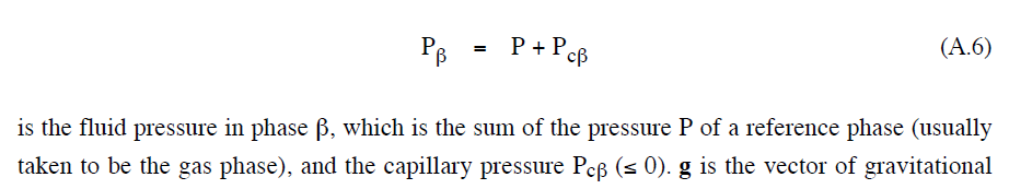
- Another simple way of adding a non-zero entry P is to allow the use of SLS>1.0 in the van Genuchten Pcap model. I'm using it not to simulate high gas entry P, as those characteristics of a cap-rock, but mainly to avoid the steep change of VG Pcap when SL approaches 1. A small non-zero gas entry P usually improves the convergence at phase transition. If the logic for a non-zero gas entry P is implemented in the EOS, the modified VG Pcap can be used instead of the BC model even for high entry pressures.
- About the failed convergence in PP. The convergence fails because of the negative P used to call the routine. The P cannot be negative, as it gives problems in the computation of several thermophysical parameters. In sub PP, for instance, a negative P gives a negative gas density DGAS, which affects the calculation of steam density D and then the partial P of steam PS.
- So, the issue is why P becomes negative? It is due to the NR iteration process itself, may be with low total P values? Or the negative P is due to the reassignement of total P for the two-phase --> L phase transition? In this case a wrong sign could be the root cause.
Capillary P in porous media raises several questions.
- we should account for the VPL when evaluating the saturation P of liquid water. In a porous medium liquid water can exist even at P lower than the saturation P for local T. At low T the effects may not be huge, while in HT geothermal applications it may make a big difference, such as in modeling two-phase conditions in steam dominated reservoirs.
- in two-phase conditions the water phase is at a P lower than that of the gas phase. Are we computing liquid water properties accounting for PL=PG+Pcap? PL may be lower than the saturation P !
- for low PG and high (abs) Pcap, PL may become negative. Water properties correlations (IFC67, IAPWS-97) are for water above the triple point. How to compute capillary liquid water properties at metastable conditions ? See Lassin et al., GCA, 2005.
Regards,
Alfredo
-
This is by far the best AI: "Alfredo Intelligence"!
Thank you, Alfredo, for this comprehensive discussion!
Stefan